Cisco Switch Commands Pdf Free Download
We are reader supported and may receive a commission when you make purchases using the links on our site
How to Configure Cisco Switch: A Step-by-Step Guide with Commands
Configuring a Cisco switch properly means your network can make connections efficiently. In this step-by-step guide, we walk you through configuring Cisco switches and look at some FAQs.
When we think of connectivity in a network, the router is probably the first device that comes to mind, but switches play a vital role in enabling network devices to communicate.
Switches can take incoming/outgoing traffic and pass it onward toward its final destination. Cisco is one of the most well-known switch vendors on the market and in this article, we're going to look at how to configure Cisco switches with PuTTY and from the command-line.
Getting Started with Cisco Switch Commands
Before we begin, get to know what hardware you're using, fire up your CLI and download PuTTY.
The first step is to check what hardware you're using before you begin. If you're using a Cisco switch you need to know what model you have. You also want to check the physical state of the device and verify that none of the cables are damaged. You can turn the router on to make sure there is no damage to the lighting/indicators.
Now that you've made sure the device is in working order you're ready to start configuring. In this guide, we're going to perform a Cisco switch configuration through the command-line interface (CLI) with the open-source SSH/Telnet client PuTTY (although you can use another tool if you prefer). If for any reason putty is not an option for your setup, you can get similar results with a PuTTY alternative.
1. Connect the Switch to PuTTY
To start configuration, you want to connect the switch console to PuTTY. You can do this by doing the following:
- Connect the switch to PuTTY with a 9-pin serial cable.
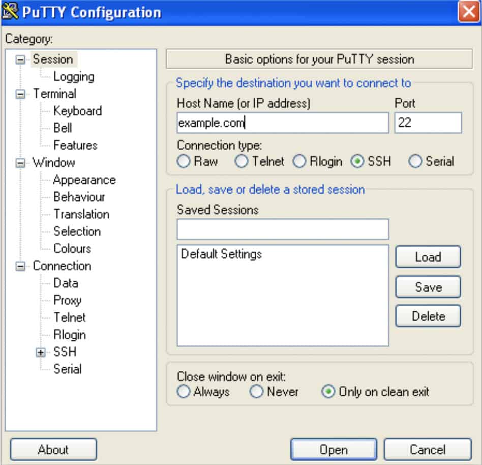
- Now open PuTTY and the PuTTY Configuration window will display. Go to the Connection type settings and check the Serial option (shown below).
- Go to the Category list section on the left-hand side and select the Serial option.
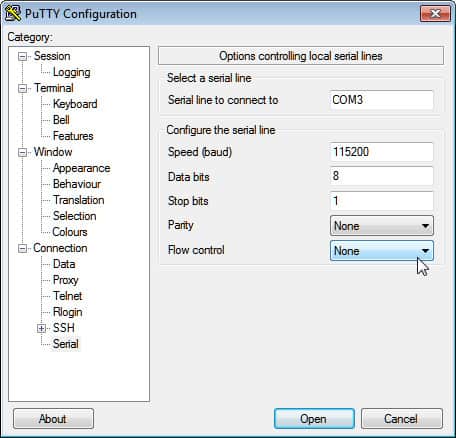
- When the options controlling local serial lines page displays enter the COM port your network is connected to in the Serial line to connect to box e.g. COM1.
- Next, enter the digital transmission speed of your switch model. For 300 and 500 Series Managed Switches, this is 115200.
- Go to the Data bits field and enter 8.
- Now go to the Stops bits field and enter 1.
- Click on the Parity drop-down menu and select the None option.
- Go to the Flow Control drop-down menu and select the None option.
Save Your Settings and Start the PuTTY CLI
To save your PuTTY settings for your next session do the following:
- Click on the Session option from the Category list on the left-hand side of the page.
- Go to the Saved Session field and enter a name for your settings e.g. Comparitech.
- Click the Save button to store the settings.
- Press the Open button at the bottom of the page to launch the CLI.
The following message will display in the command prompt:
Switch>
2. Enter Privileged EXEC Mode and Set a Hostname for the Switch
Type in the enable command to enter privileged EXEC mode (you don't need a password at this stage because you're under the default configurations which don't have one!):
Enable
Next, enter Global Configuration Mode and enter the following command:
Switch# configure terminal Switch(config)#
You can make the switch easier to locate in the network by assigning a hostname. Enter the following command to assign a hostname:
Switch(config)# hostname access-switch1 access-switch1(config)#1
3. Assign a Password to the Switch
Once you've assigned a hostname you will want to create a password to control who has access to the privileged EXEC mode (to prevent everyone from being able to log in). To assign an administrator password to enter the following command:
access-switch1(config)# enable secret COMPARI7ECH
Remember to pick a strong password so that it's harder to figure out.
4. Configure Telnet and Console Access Passwords
The next step is to configure passwords for Telnet and console access. Configuring passwords for these is important because it makes your switch more secure. If someone without authorization gains telnet access then it puts your network at serious risk. You can configure passwords by entering the following lines (See the top paragraph for Telnet and the bottom paragraph for Console access).
Telnet
access-switch1(config)# line vty 0 15 access-switch1(config-line)# password COMPARI7ECH access-switch1(config-line)# login access-switch1(config-line)# exit access-switch1(config)#
Console
access-switch1(config)# line console 0 access-switch1(config-line)# password COMPARI7ECH access-switch1(config-line)# login access-switch1(config-line)# exit access-switch1(config)#
5. Configure IP Addresses With Telnet Access
The next step is to decide which IP addresses will have access to Telnet, and add them with the PuTTY CLI. To select permitted IP's enter the following command (replace the listed IPs with the IPs of the components you want to grant permission to):
access-switch1(config)# ip access-list standard TELNET-ACCESS access-switch1(config-std-nacl)# permit 216.174.200.21 access-switch1(config-std-nacl)# permit 216.174.200.21 access-switch1(config-std-nacl)# exit
You can also configure your network's access control lists (ACLs) to virtual terminal (VTY) lines. ACLs ensure that only the administrator can connect to the router through Telnet.
access-switch1(config)# line vty 0 15 access-switch1(config-line)# access-class TELNET-ACCESS in access-switch1(config-line)# exit access-switch1(config)#
6. Configure a Network Management IP address (or Management Interface)
Next, you need to configure a network management IP address. Switches don't come with an IP address by default, meaning that you can't connect to it with Telnet or SSH. To solve this problem you can select a virtual LAN(VLAN) on the switch and create a virtual interface with an IP address. You can do this by entering the following command:
access-switch1(config)# interface vlan 1 access-switch1(config-if)# ip address 10.1.1.200 255.255.255.0 access-switch1(config-if)# exit access-switch1(config)#
The new IP management address is located in VLAN1, which other computers will now use to connect.
7. Assign a Default Gateway to the Switch
At this stage, you want to assign a default gateway to the switch. The default gateway is essentially the address of the router that the switch will be communicating with. If you don't configure a default gateway then VLAN1 will be unable to send traffic to another network. To assign the default gateway, enter the command below (change the IP address to that of your router).
access-switch1(config)# ip default-gateway 10.1.1.254
8. Disable Unused Open Ports
As a best practice, it is a good idea to disable any unused open ports on the switch. Cyber-criminals often use unsecured ports as a way to breach a network. Closing these ports down reduces the number of entry points into your network and makes your switch more secure. Enter the range of ports you want to close by entering the following command (you would change 0/25-48 to the ports that you want to close):
access-switch1(config)# interface range fe 0/25-48 access-switch1(config-if-range)# shutdown access-switch1(config-if-range)# exit access-switch1(config)#
9. Save Your System Configuration Settings
Once you've finished configuring the router it's time to save your system configuration. Saving the configuration will make sure that your settings are the same when you open up your next session. To save enter the following command:
access-switch1(config)# exit access-switch1# wr
Always remember to save any changes to your settings before closing the CLI.
10. Configure NetFlow to Manage Your Cisco Switch (Optional)
It is also a good idea to use a network traffic analyzer to monitor network traffic. As a Cisco device, your switch will have the communication protocol NetFlow. However, it must be configured first. You can configure NetFlow by completing the four steps below. Before we begin, enter Global Configuration Mode by executing the following command:
Switch# configure terminal
Create a flow record
- The first step is to create a flow record (you can change the name). You can do this by entering the following command:
#flow record Comparitechrecord
- After you've entered the previous command you need to set the IPv4 source address, IPv4 destination address, iPv4 protocol, transport source-port, transport destination-port, IPv4 dos, interface input, and interface output. You can do this by entering the following command:
Switch# match ipv4 source address Switch# match ipv4 destination address Switch# match ipv4 protocol Switch# match transport source-port Switch# match transport destination-port Switch# match ipv4 tos Switch# match interface input Switch# collect interface output
- To finish configuring the flow record and define the type of data you're going to collect, enter the following switch configuration commands:
Switch# collect interface output Switch# collect counter bytes Switch# collect counter packets Switch# collect timestamp sys-uptime first Switch# collect timestamp sys-uptime last
Create the Flow Exporter
- You must now create the flow exporter to store the information that you want to export to an external network analyzer. The first step is to name the flow exporter:
Switch# flow exporter Comparitechexport
- Enter the IP address of the server your network analyzer is on (Change the IP address):
Switch# destination 117.156.45.241
- Configure the interface that you want to export packets with:
Switch# destination source gigabitEthernet 0/1
- Configure the port that the software agent will use to listen for network packets:
Switch# transport UDP 2055
- Set the type of protocol data that you're going to export by entering this command:
Switch# export-protocol netflow-v9
- To make sure there are no gaps in when flow data is sent enter the following command:
Switch# template data timeout 60
Create a Flow Monitor
- Once you've configured the flow exporter it is time to create the flow monitor. Create the flow monitor with the following command:<
Switch# flow monitor Comparitechmonitor
- Associate the flow monitor with the flow record and exporter we configured earlier:
Switch# record Comparitechrecord
Switch# exporter Comparitechexport
- To make sure that flow information is collected and normalized without a delay, enter the following command:
Switch# cache timeout active 60
Switch# cache timeout inactive 15
- Enter the exit command:
Switch# exit
- You need to input the interfaces that will collect the NetFlow data. If this is an ethernet interface you would enter the following:
Switch# interface gigabitEthernet 0/1
- Use the following command to configure NetFlow on multiple interfaces (the input command will still collect data in both directions):
Switch# ip flow monitor Comparitechmonitor input
- If you want to collect NetFlow data on only one interface then you must use the input and output command. So you would enter the following:
Switch# ip flow monitor Comparitechmonitor input
Switch# ip flow monitor Comparitechmonitor output
- Exit configuration mode by entering the following command:
Switch# exit
- Save your settings to finish.
Configure a Cisco Switch for Peace of Mind!
Completing simple tasks like configuring passwords and creating network access lists controls who can access the switch can enable you to stay secure online. Incomplete or incorrect configurations are a vulnerability that attackers can exploit.
Configuring a Cisco switch is only half the battle, you also have to regularly monitor its status. Any performance issues with your switch can have a substantial impact on your users.
Using a network monitoring tool and network analyzer can help you to monitor switches remotely and review performance concerns. Taking the time out of your day to configure a switch and assign strong passwords gives you peace of mind so that you can communicate safely online.
Cisco Switch Configuration & Commands FAQs
How to configure a trunk port on a Cisco 2960 switch?
To configure a trunk port on a Cisco 2960 switch:
- Enter configuration mode:
configure terminal
- Specify the port to use:
interface <interface-id>
- Configure the port as a Layer 2 trunk:
switchport mode {dynamic {auto | desirable} | trunk} These options mean:
- dynamic auto – The Default. Creates a trunk link if the neighboring interface is set to trunk or desirable mode.
- dynamic desirable – Creates a trunk link if the neighboring interface is set to trunk, desirable, or auto mode.
- trunk – Sets the interface in permanent trunking mode.
- Specify a default VLAN to use for back up. This is optional:
switchport access vlan <vlan-id>
- Specify the native VLAN:
switchport trunk native vlan <vlan-id>
- Exit the config mode:
end
How do I set a static IP on a Cisco switch?
A problem with the GUI interface of Cisco switches makes it impossible to assign a static IP address to an interface. Follow these steps for a workaround:
- Create a text file on your PC. It doesn't matter where you save it or what you call it, but make sure you remember where it is. Substitute real values for the tokens shown in angle brackets (<>) below. The text in the file should be:
Config t Interface <VLAN ID> No ip address DHCP Y No ip address <old IP address> IP address <new IP address> <subnet mask> Exit IP default-gateway <gateway IP address>
- Access the admin menu of the switch for Switch Management.
- In the menu, click on Administration, then File Management, and then select File Operations.
- In the File Operations screen, set the following:
- Operation Type: Update File
- Destination File Type: Running Configuration
- Copy Method: HTTP/HTTPS
- File Name: (Browse to select the file you created on your PC).
- Click on Apply.
These steps will create a static IP address, which you can check by going from the main menu to IP Configuration > IPv4 Interface.
Do I have to configure a Cisco switch before it gets to work?
No. The typical Cisco switch is ready to go out-of-the-box. However, you might want to change some parameters to customize its operations.
Posted by: alisaalisabilliare0273479.blogspot.com
Source: https://www.comparitech.com/net-admin/configure-cisco-switches/

Post a Comment for "Cisco Switch Commands Pdf Free Download"